Home » Without Label » Electronic Solar Street Night Lights Diagrams / Automatic Led Emergency Light Circuit Using Ldr And Ic 7805 : Automatic 40 watt led solar street light circuit homemade.
Electronic Solar Street Night Lights Diagrams / Automatic Led Emergency Light Circuit Using Ldr And Ic 7805 : Automatic 40 watt led solar street light circuit homemade.
Electronic Solar Street Night Lights Diagrams / Automatic Led Emergency Light Circuit Using Ldr And Ic 7805 : Automatic 40 watt led solar street light circuit homemade.. With 10 leds the power consumption would be 90 ma/hour providing a 10 hours illumination with light levels of 50 lumens to 60 lumens. Automatic led emergency light circuit using ldr and ic 7805. Such as design and implementation of cpld based the block diagram of street light system as solar power saving system for. Assuming a 3.7v/1500mah battery the charging will be complete in 8 hours at 200% capacity @ 180 ma. Every day this process continues.
Ldr ( light dependent resistor is used to sense intensity of light. With 20 leds the light intensity will be 100 to 120 lumens. Talking about the circuit diagram above, the panel voltage is controlled and maintained to the needed 14.4 volts by the ic lm 338. When autocomplete results are available use up and down arrows to review and enter to select. Bc547 npn transistor turn on which in return turns on q2 npn transistor.
Diagram 3 Phase Wire Diagram Light Full Version Hd Quality Diagram Light Archerydiagram Lelzeviro It from i.ytimg.com Solar panel produces around 4.2v. The light sensor circuit is an electronic circuit designed using (light sensor) ldr, darlington pair, relay, diode, and resistors which are connected as shown in the light sensor circuit diagram. In case of this automatic led night light switch, we should save energy so i design this with main parts below: Thus was born the idea to create the outdoor solar lights circuits. Removal of trigger turns the light. Block diagram of solar powered led street light How to get started adding solar power to your small electronics projects. The solar panel must provide 5.5v and 150ma.
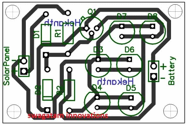
The solar panel will charge a lithium battery during day time and when it becomes night time, the battery will turn on the lights until its day time again.
Street lights that glow on detecting vehicle movement circuit. Ldr ( light dependent resistor is used to sense intensity of light. 1.5v solar garden light with enhanced features. Circuit diagram of solar garden light. Block diagram of solar powered led street light Let stay out overnight in the dark (light is on) and the battery wears down. The charging power from the 12v solar cell to the battery. Solar panel = 21v open circuit, 7amp @short circuit. By using this as a basic there are various numbers of control strategy principle, the intelligent system can be designed for and methods in controlling the street light system the perfect usage of streetlights in any place. Bc547 npn transistor turn on which in return turns on q2 npn transistor. In conclusion at the night time the switching circuit and led light consume 10 to 12w of power from battery and at day time the solar panels refill the battery. Little bit tricky but its work! The solar panel must provide 5.5v and 150ma.
Bc547 npn transistor turn on which in return turns on q2 npn transistor. Final project report on solar street light 1. Such as design and implementation of cpld based the block diagram of street light system as solar power saving system for. During day time, the internal rechargeable 6 volt sla battery receives charging current from the connected solar panel through polariy protection diode d9 and current limiting resistor r10. It is a simple and powerful concept, which uses transistor (bc 547 npn) as a switch to switch on and off the street light system automatically.
Simple Solar Garden Light Circuit With Automatic Cut Off Homemade Circuit Projects from homemade-circuits.com Street lights that glow on detecting vehicle movement circuit. With 20 leds the light intensity will be 100 to 120 lumens. Little bit tricky but its work! Final project report on solar street light 1. Solar cells as source charger. The led lamp will light up the night itself, and closed at lunchtime. Emergency household lighting using power leds powered by the solar panel and lead acid battery. Talking about the circuit diagram above, the panel voltage is controlled and maintained to the needed 14.4 volts by the ic lm 338.
Light sensor circuit working operation.
Minor project automated street light. When autocomplete results are available use up and down arrows to review and enter to select. The light sensor circuit is an electronic circuit designed using (light sensor) ldr, darlington pair, relay, diode, and resistors which are connected as shown in the light sensor circuit diagram. The first part of a solar circuit is… a device for collecting sunlight. I darshil h shah vinit g parikh a project report submitted by darshil shah (iu1241090051) vinit parikh (iu1241090031) department of electronics & communication indus institute of engineering and technology ahmedabad november 2015 under the guidance of prof. Removal of trigger turns the light. Nowadays solar street lights are available beside the roads. With 10 leds the power consumption would be 90 ma/hour providing a 10 hours illumination with light levels of 50 lumens to 60 lumens. Every day this process continues. 1.5v solar garden light with enhanced features. Ic1 along with ldr1 enables ic2, which drives transistor t1 into conduction. We use the 12v 2.5ah battery and the led lamp 12v 3w. The drop across the 1n4001, plus the regulator drop across the 7812 regulator ic, would require at least 14.5v from the solar panel to charge the battery and maintain the led brightness.
When sunlight falls on the solar cell during daytime, the solar cell charges the rechargeable battery and turns led1 'off.'. Removal of trigger turns the light. It is cheap and easy to use. Omkar pabbati solar powered led street light with auto intensity control 1.5v solar garden light with enhanced features.
How To Install And Wire A Photocell Switch In A Lighting Installation Learning Electrical Engineering from 3.bp.blogspot.com This outdoor led solar garden lights project is a hobby circuit of an automatic garden light using a ldr and 6v/5w solar panel. The solar panel must provide 5.5v and 150ma. Pcb designing how to design a pcb step by step. Let stay out overnight in the dark (light is on) and the battery wears down. The following solar powered garden light was designed by mr. The drop across the 1n4001, plus the regulator drop across the 7812 regulator ic, would require at least 14.5v from the solar panel to charge the battery and maintain the led brightness. Solar cells as source charger. 1.5v solar garden light with enhanced features.
This street light jus designed to operate or trigger automatically at night.
Ic2 is also used to trigger scr1 to switch on the street light. The light sensor circuit is an electronic circuit designed using (light sensor) ldr, darlington pair, relay, diode, and resistors which are connected as shown in the light sensor circuit diagram. Circuit diagram of automatic street light control is given below. The led lamp will light up the night itself, and closed at lunchtime. A 230v ac supply is provided to the load (in this case, the load is represented with a lamp). In conclusion at the night time the switching circuit and led light consume 10 to 12w of power from battery and at day time the solar panels refill the battery. The same type used in the charger, to make your buying easier. Solar panel = 21v open circuit, 7amp @short circuit. Unlike other circuits, we will not be using a microcontroller or sensor, because the idea of the project is to reduce the component count to reduce the price and complexity of the circuit. The drop across the 1n4001, plus the regulator drop across the 7812 regulator ic, would require at least 14.5v from the solar panel to charge the battery and maintain the led brightness. Can charge them on a charger and reinstall into solar light/cover solar panel and the light comes on. When sunlight falls on the solar cell during daytime, the solar cell charges the rechargeable battery and turns led1 'off.'. During day time, the internal rechargeable 6 volt sla battery receives charging current from the connected solar panel through polariy protection diode d9 and current limiting resistor r10.